
The Most Expensive Mistakes in Manufacturing Happen Before the First Part is Fabricated
70% of a product's manufacturing costs are locked in during the design phase. While the actual design work may represent only a fraction of your total budget, the decisions made at the CAD station dictate the entire downstream reality, from material waste and specialized tooling to assembly labor and shipping logistics. A finished print is often just the beginning of a high-stakes game of consequences. If a design doesn’t respect the physical limits of the shop floor, those costs compound.
We refer to this as the Rule of 10. If it costs $1 to fix a design flaw on a print, it will cost $10 to fix it during prototyping, $100 during production, and $1,000 once it reaches your customer. Because of this, most production nightmares, like the ones that blow budgets and push lead times into next month, are actually locked in long before the first sheet of metal is loaded onto the laser.
In this blog, we’ll break down the specific engineering choices that act as "quiet" cost drivers and provide a checklist of high-impact design decisions you can optimize today so your project moves seamlessly from CAD to completion.
7 Design Decisions That Quietly Inflate Cost and Lead Time
Before beginning a production run, it’s essential to understand how geometric choices influence machine behavior. These are the most frequent hidden pitfalls we encounter during print reviews — issues that often seem minor on a screen but create significant friction once physical material is involved.
By addressing these seven areas, you can transition from a fix-it-later mentality to a proactive engineering strategy that protects both your timeline and your bottom line.
1. Respecting the Physics of Bend Relief and Hole Proximity
One of the most frequent lead-time killers is the placement of holes, slots, or notches too close to a bend line. When sheet metal is formed, the material physically stretches and flows around the radius. If a hole is located within this stretch zone, the press brake force will pull the material, causing the hole to distort into an unsightly egg shape.
To fix this after the fact, a fabricator is forced to add secondary operations, such as drilling or reaming the feature after the part has been bent, which can double the labor time for that specific feature.
To avoid this, designers should make sure that the hole edges are located at least twice the material thickness plus the bend radius from any bend line.
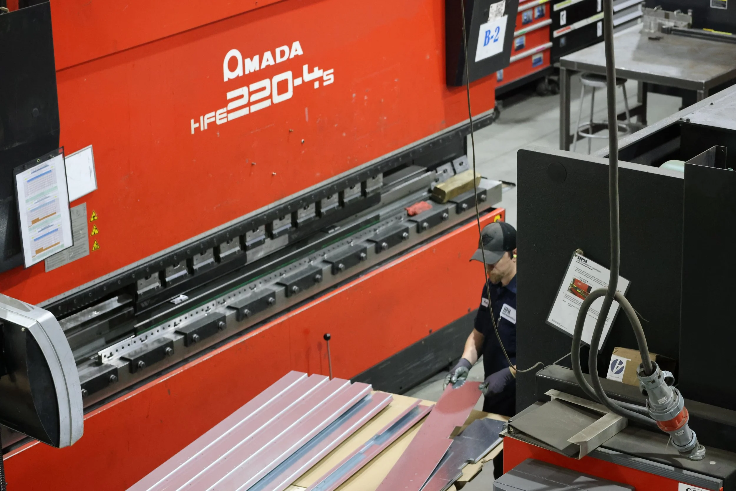
2. The High Cost of Non-Standard Bend Radii
Another common mistake is specifying a mathematically perfect bend radius in CAD that doesn't align with standard shop floor tooling. For example, if your design calls for a 0.040" radius but the fabricator’s standard library jumps from 0.032" to 0.060", you have created an immediate bottleneck.
The manufacturer must either air-bend the part, which can lead to less predictable tolerances, or order custom tooling, which adds thousands to the setup cost and weeks to the lead time. Aligning your CAD K-Factors and radii with your partner’s tool library early is the simplest way to get rapid, repeatable production.
3. The Burden of Over-Tolerancing Non-Critical Dimensions
It’s often a reflex for engineers to apply a blanket +/- .005" tolerance across an entire print. However, precision is a commodity that is purchased with time. Every tight tolerance requires slower machine speeds, more frequent manual measurements, and a higher probability of scrap. When a fabricator sees over-toleranced prints, they must bake risk insurance into the unit price to cover the inevitable fallout.
By using functional tolerancing, tightening only the dimensions critical for fit, seal, or safety, you allow the fabricator to optimize for speed on non-critical features, lowering your overall cost per part.
4. Supply Chain Friction from Exotic Hardware
Hardware selection is often treated as an afterthought, yet it is a primary driver of production halts. Specifying a specialized self-clinching fastener (PEM nut) that isn't stocked by local distributors can stop a high-volume production line in its tracks. It’s a frustrating reality when a $10,000 assembly is delayed by four weeks because of a 0.25-cent non-standard fastener.
Consulting with your manufacturing partner on common-carrier hardware enables you to use readily available fasteners compatible with high-speed automated insertion equipment, so your assembly phase is as fast as your cutting phase.
5. Material Inefficiency and the Logic of the Nest
The dimensions of your part are directly related to the available raw material sheets on the market. A part designed at 25 inches wide may appear efficient, but because standard sheets are typically 48 or 60 inches wide, that extra inch prevents the fabricator from nesting two parts side by side.
This results in significantly more scrap metal that you, the customer, ultimately pay for. Designing with standard sheet sizes in mind and optimizing part geometry to allow for tighter nesting can drastically reduce raw material spend, which is often the largest single component of a part's total cost.
6. The Complexity of Multi-Stage Finishing
A common design trap is assuming that complex finishing, like masking specific areas for powder coating or applying different finishes to the same surface, is a simple last step. In reality, complex finishing requirements often lead to high reject rates at the final inspection. Each masking requirement adds manual labor and a point of potential failure.
If your part requires aesthetic perfection alongside rugged protection, consider designing the assembly as separate components that can be finished individually before final joinery. This modular approach to finishing reduces risk and creates a more consistent final appearance.
7. Designing for Assembly Ergonomics and Tool Clearance
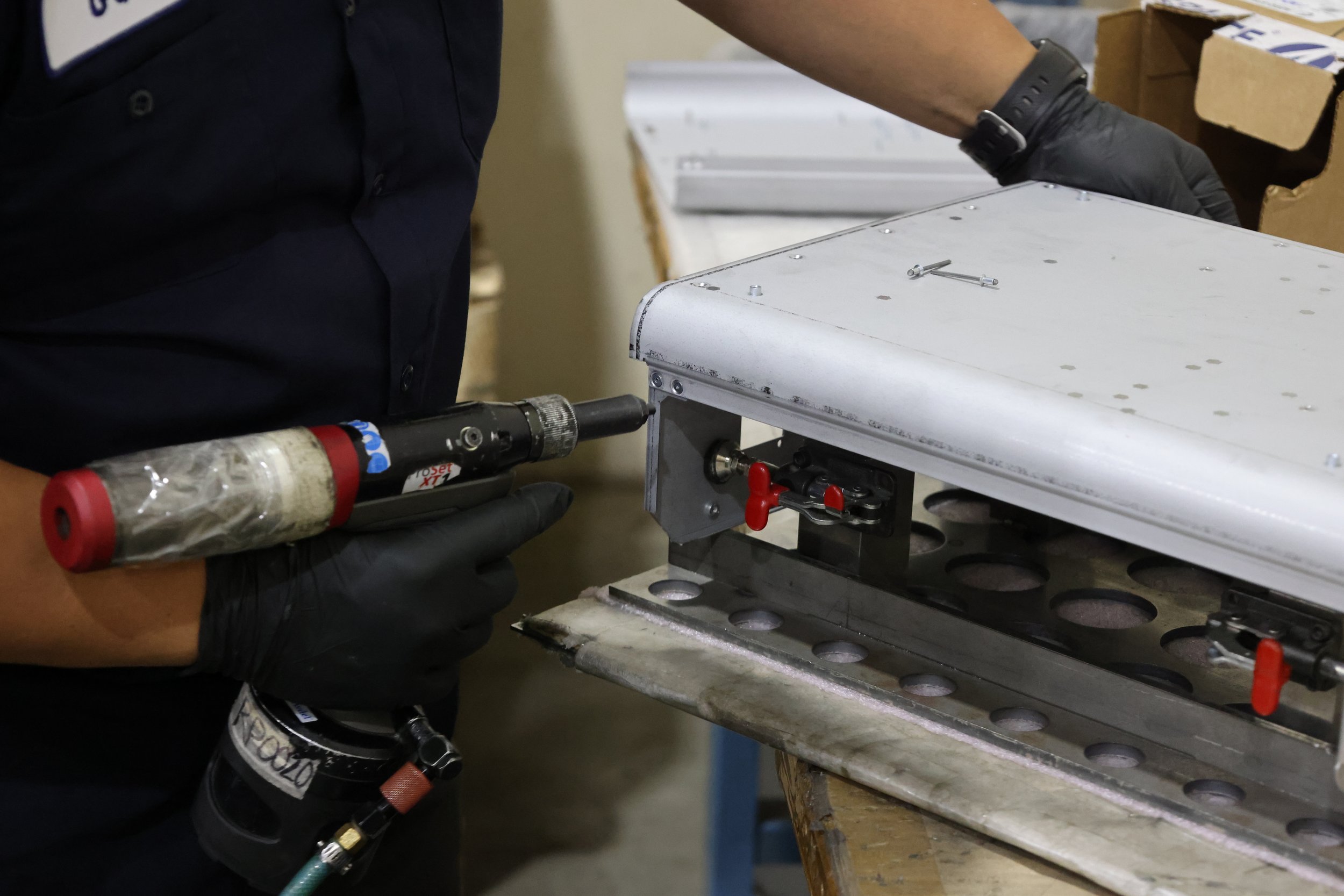
A design is only successful if it can be built efficiently by a human or a machine. We often see enclosures where a fastener is tucked so deep into a corner that a standard pneumatic tool cannot reach it. If a technician has to use a specialized, angled wrench or perform a blind installation, your assembly labor costs will skyrocket.
Beyond just the cost, poor tool clearance increases the likelihood of damage like scratched powder coating or stripped threads during the final stages of production. Designing for generous tool clearance so that your parts move through the assembly floor as quickly as they move through the laser.
How HPM Intercepts These Problems Early
While these seven points provide a strong foundation, the most effective way to eliminate “locked-in" costs is through a dedicated fabrication partnership. We don't just take your CAD file and hit "print”. Our engineering-first culture is built on a quality heritage of accuracy and discipline.
With a team of 7 full-time engineers, we act as an extension of your design department, performing rigorous Design for Manufacturing (DFM) reviews long before production begins. We challenge designs early from the component level through the system level to optimize them for the realities of the shop floor. By intercepting these quiet risks early, we’re able we manufacture cost savings and peace of mind.
Is your next design optimized for the shop floor? Contact HPM today to start an early-stage design consultation and ensure your project is built for success.